Optical Power Meter Guide: Device Types, Measurement Methods, Features and Fiber Testing
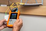
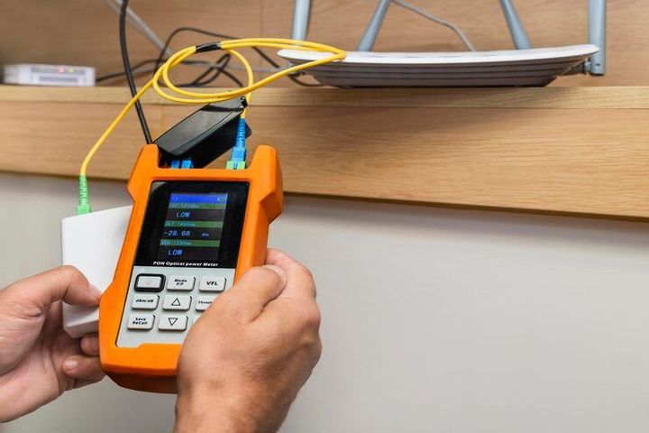
An optical power meter is an instrument used to measure the optical power carried through a fiber-optic link. It is commonly used with a light source to determine how much optical signal reaches the receiving end of a fiber. The measurement is generally expressed in dBm or watts, depending on the instrument and application.
Context
An optical power meter is an instrument used to measure the optical power carried through a fiber-optic link. It is commonly used with a light source to determine how much optical signal reaches the receiving end of a fiber. The measurement is generally expressed in dBm or watts, depending on the instrument and application.
Fiber-optic communication uses light instead of electrical signals to transmit information. As fiber networks became more widely used in telecommunications, data centers, industrial facilities, and control systems, technicians needed practical instruments for checking signal levels, connector losses, cable attenuation, and link performance.
An optical power meter normally contains a photodetector, measurement electronics, a display, and a connector interface. The detector converts incoming optical energy into an electrical signal that the instrument processes into a power reading.
How an optical power meter works
A basic fiber test involves connecting a calibrated optical source to one end of a fiber and an optical power meter to the other. The source sends light through the fiber, while the meter measures the power received.
The difference between a reference measurement and a subsequent measurement can be used to determine insertion loss. This approach is important when checking whether connectors, splices, adapters, or sections of fiber are introducing excessive attenuation.
| Measurement | Typical purpose |
|---|---|
| Optical power | Determines received optical signal level |
| Insertion loss | Determines signal reduction through a component or link |
| Reference power | Establishes a comparison level |
| Attenuation | Indicates reduction of optical power along a path |
| Wavelength | Identifies the optical wavelength being measured |
| dBm | Logarithmic representation of optical power |
Where optical power meters are used
Optical power meters are used across several environments. Telecommunications networks, data centers, enterprise communication systems, industrial automation installations, and fiber-based sensing systems can all require optical measurements.
Fiber networks can also appear in manufacturing environments where machinery is connected through industrial communication infrastructure. Textile production is one example. Modern weaving operations can contain electronic controls, sensors, monitoring equipment, and networked machinery around different types of looms.
Waterjet looms, air jet looms, rapier looms, and Jacquard looms have different mechanisms for inserting or controlling yarn, but their surrounding factory infrastructure can include electronic control and communication systems. An optical power meter is not a tool for measuring the weaving process itself; it can instead be relevant when fiber-optic communication links are used within the wider industrial environment.
Importance
Fiber-optic systems are designed to transmit light efficiently, but signal power can decrease as light travels through a cable and its connected components. Bends, contamination, poor connections, damaged fiber, incompatible components, and excessive cable length can contribute to attenuation.
An optical power meter provides a direct measurement of the optical signal reaching a particular point. This can help technicians distinguish between a transmission problem and other possible issues within a communication system.
Why fiber testing matters
Fiber testing is relevant during installation, commissioning, maintenance, troubleshooting, and periodic network assessment. A power reading can show whether an optical signal is present and whether its level falls within the expected operating range for the equipment being tested.
A single power measurement, however, does not provide a complete picture of fiber condition. More detailed testing may require an optical time-domain reflectometer, an optical loss test set, a visual fault locator, or an inspection microscope.
Optical power meter and textile machinery
Industrial networking has become increasingly connected with automated machinery. In a textile facility, communication infrastructure may support control systems around waterjet looms, air jet looms, rapier looms, and Jacquard looms.
The weaving machines themselves perform different functions:
- Waterjet looms use water to carry the weft yarn across the shed.
- Air jet looms use a controlled air stream for weft insertion.
- Rapier looms use a rigid or flexible rapier mechanism to carry the weft.
- Jacquard looms provide individual or grouped control of warp yarns to create complex patterns.
Optical fiber can be part of the communication infrastructure around such equipment where industrial networks require high-speed data transmission or resistance to electromagnetic interference. In these situations, an optical power meter can be used to check the fiber link rather than the mechanical performance of the loom.
Recent Updates
Fiber testing has continued to evolve alongside higher-speed communication networks, denser data-center infrastructure, and more complex optical systems. Current measurement practices place considerable attention on repeatability, calibration, connector condition, measurement uncertainty, and appropriate test methods.
IEC 61300-3-4:2023 describes methods for measuring attenuation of optical components and includes an insertion method involving a light source and power meter. The standard also addresses measurement approaches for different fiber and component configurations.
Another relevant development is the continued refinement of measurement procedures for optical components. IEC 61300-3-14:2025, for example, addresses error and repeatability in attenuation settings for variable optical attenuators and references IEC 61315 for calibration of fiber-optic power meters.
Higher-density fiber systems
As communication systems use more fibers within smaller physical spaces, measurement equipment increasingly needs to work with multiple connector formats and dense fiber assemblies. In 2026, IEC 61300-3-30 was updated to address endface geometry measurements for rectangular multifiber ferrules, including interfaces associated with higher-fiber-count configurations.
This development is relevant to fiber testing because connector geometry can affect how optical fibers align during connection. Power measurement remains one part of a broader testing process that may also involve connector inspection and loss measurement.
Calibration and measurement confidence
Calibration remains an important part of optical measurement. IEC 61315:2019 specifies calibration principles for fiber-optic power meters measuring radiant power from sources such as laser diodes, LEDs, and fiber-type sources. It also includes provisions concerning dB conversion.
These developments show a broader movement toward more controlled and repeatable optical measurements rather than relying only on whether a network link appears to function.
Laws or Policies
Optical power meters are generally measurement instruments rather than communication networks themselves, so their regulatory treatment can differ according to their intended application and jurisdiction.
Telecommunications and industrial installations may be affected by separate rules concerning electrical safety, electromagnetic compatibility, radio equipment, workplace safety, optical radiation, or telecommunications infrastructure. The specific requirements depend on the equipment and environment.
International technical standards are commonly used to establish consistent test methods. IEC 61300-3-4 addresses attenuation measurements for fiber-optic interconnecting devices and passive components, while IEC 61315 addresses calibration of fiber-optic power meters.
For installed multimode fiber cabling, IEC 61280-4-1 describes attenuation measurement procedures covering environments such as commercial buildings, industrial facilities, data centers, and outside-plant installations.
Compliance requirements can also apply to the larger communication system rather than the meter itself. Organizations working with regulated telecommunications or industrial infrastructure therefore need to consider the rules applicable to their particular installation.
Tools and Resources
Optical power measurement is usually more effective when combined with other fiber-testing instruments and documentation.
Optical light source
A calibrated optical light source transmits light at a specified wavelength into the fiber. When paired with a power meter, it can be used for insertion-loss measurements.
Optical time-domain reflectometer
An optical time-domain reflectometer, commonly called an OTDR, sends optical pulses into a fiber and analyzes returned signals. It can help identify events such as splices, connectors, bends, and breaks along a cable.
Visual fault locator
A visual fault locator uses visible light to help identify certain breaks, severe bends, or connection problems. It is generally used as a complementary diagnostic tool rather than as a substitute for quantitative optical power measurement.
Fiber inspection tools
Inspection microscopes and automated inspection equipment can be used to examine connector endfaces. Dirt or damage on an endface can affect optical coupling and introduce additional attenuation.
Testing documentation
A structured fiber-testing record can contain:
- Fiber identification
- Test wavelength
- Reference power
- Measured power
- Calculated loss
- Connector information
- Test equipment identification
- Calibration information
- Date of measurement
- Technician or test location
Keeping these details together helps make measurements easier to compare across different stages of a fiber installation.
Standards and technical references
The International Electrotechnical Commission publishes technical standards covering many aspects of fiber-optic measurement. IEC 61300-3-4, IEC 61315, and IEC 61280-4-1 are useful references for understanding attenuation measurement, power-meter calibration, and installed multimode fiber testing.
FAQs
What is an optical power meter used for?
An optical power meter measures the amount of optical power reaching its detector. In fiber testing, it can be used to check signal levels, establish reference measurements, and determine attenuation or insertion loss when paired with a suitable optical source.
How does an optical power meter measure fiber loss?
A reference power level is first established using an appropriate optical source and measurement arrangement. The fiber or component is then introduced into the test path, and the change in measured power can be used to calculate insertion loss.
What features should an optical power meter have?
Relevant features can include wavelength selection, an appropriate measurement range, compatible fiber connectors, dBm and watt measurement modes, reference measurement functions, memory, data connectivity, and calibration information. The appropriate features depend on the fiber type and testing application.
Can an optical power meter test fiber used around looms?
Yes, when the loom environment contains fiber-optic communication links, an optical power meter can be used to measure those links. This can apply to industrial networks associated with waterjet looms, air jet looms, rapier looms, and Jacquard looms, although the instrument does not measure the mechanical weaving process itself.
Is an optical power meter enough for complete fiber testing?
No. An optical power meter provides an important measurement of optical signal power, but comprehensive fiber testing may require additional instruments. OTDR testing, connector inspection, light-source measurements, and other procedures can provide information that a power meter alone cannot provide.
Conclusion
An optical power meter is an important instrument for measuring optical signal power and assessing attenuation in fiber-optic systems. Digital measurement functions, calibration practices, connector compatibility, wavelength selection, and appropriate testing methods all influence how measurements are interpreted. Fiber testing can support communication infrastructure in telecommunications, data centers, industrial facilities, and networked manufacturing environments, including systems surrounding different types of looms. Current standards continue to refine measurement procedures, calibration, attenuation testing, and connector evaluation.